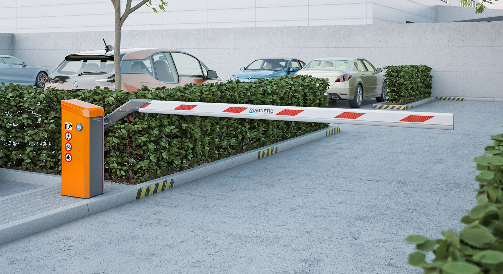
All about Wedge Barriers

14 and the surface 12 to which the obstacle 10 is protected might be made from concrete - Wedge Barriers. 2, the barrier 10 is mounted to or includes an anchor or subframe (e. g., anchor 30 displayed in FIG. 2 )safeguarded underneath the surface area 12. The bather 10 may be bolted to the support or protected to the anchor by other mechanical fasteners. In the detailed personification, the barrier 10 consists of a wedge plate 16, that includes a section that is considerably identical with the surface 12 when the obstacle 10 remains in the withdrawed setting. Simply put, cars or people may pass over the obstacle 10 when the obstacle 10 is in the retracted position and experience minor elevation about the surface area 12 while on the barrier 10. As gone over thoroughly listed below, when the barrier 10 is in the released position, the wedge plate 16 is held and supported in an elevated placement by a training system of the barrier 10. Additionally, the components 18 might be bolted or otherwise mechanically coupled to one an additional. In this way, repair or replacement of one or more parts 18 may be streamlined and streamlined. That is, repair service or replacement of solitary parts
18 may be done extra swiftly, conveniently, and expense successfully. FIG. In certain personifications, the anchor 30 may be a steel framework consisting of plates, beam of lights(e. g., I-beams ), and/or various other structures that are secured within the foundation 14, which may be concrete. At the surface 12, a top side 28 of the anchor 30 might go to the very least partially revealed
, consequently enabling the add-on of the barrier 10 to the anchor 30. g., threaded holes)in one or even more beam of lights or plates of the anchor 30 may be exposed to the surface area 12. In this way, bolts 32 or various other mechanical bolts may be made use of to secure the barrier 10 to the anchor 30. As the obstacle 10 is placed to the surface 12 of the foundation 14, collection of particles and other product below the obstacle might be decreased, and components of the bather 10 may not be exposed to listed below quality settings. As shown by reference numeral 52, the lifting system 50 consists of components got rid of underneath the wedge plate 16. For instance, the components 52 beneath the wedge plate 16 may consist of an electromechanical actuator, a web cam, several webcam surface areas, etc. In addition, the training device 50 consists of a springtime assembly 54
The springtime rod 58 is coupled to a webcam(e. g., webcam 80 received FIG. 4) of the lifting device 50. The springtimes 60 disposed about the spring pole 58 are kept in compression by springtime sustains 62, consisting of a fixed springtime assistance 64. That is, the set springtime support 64 is fixed about the foundation 14 and the rest of the bather 10.
Wedge Barriers for Beginners
g., spring assistance 65 )might be taken care of to the end of the springtime rod 58 to allow compression of the springs 60. As the springtimes 60 are pressed between the spring sustains 62, the spring setting up 54 produces a pressure acting on the camera coupled to the springtime pole 58 in a direction 66. The remaining pressure applied to
the cam camera deploy the wedge plate 16 may might provided offered an electromechanical actuator 84 or other various other. The springtime setting up 54 and the actuator 84(e. g., electromechanical actuator)might operate with each other to convert the webcam and raise the wedge plate 16.
As mentioned above, the spring assembly 54 puts in a consistent force on the webcam, while the electromechanical actuator may be regulated to exert his comment is here a variable force on the webcam, consequently making it possible for the lifting and lowering( i. e., releasing and withdrawing )of the wedge plate 16. In particular embodiments, the continuous force used by the springtime setting up 54 might be flexible. g., electromechanical actuator) is disabled. As will be appreciated, the spring setting up 54 might be covered and safeguarded from debris or other aspects by a cover plate(e. g., cover plate 68 revealed in FIG. 4) that might be substantially flush with the elevated surface 38 of the foundation 14. As mentioned above, in the deployed position, the wedge plate 16 serves to block gain access to or traveling past the barrier 10. For instance, the obstacle 10(e. g., the wedge plate 16 )may block pedestrians or vehicles from accessing a home or pathway. As gone over above, the barrier 10 is attached to the support 30 protected within the structure 14,
front brackets 71. Therefore, the link settings up 72 might pivot and revolve to make it possible for the collapse and expansion of the linkage assemblies 72 during retraction and click this site implementation of the bather 10. The affiliation assemblies 72 cause motion of the wedge plate 16 to be restricted. For example, if an automobile is taking a trip in the direction of the deployed wedge plate 16(e. For example, in one condition, the safety and security legs 86 might be extended duringupkeep of the obstacle 10. When the safety and security legs 86 are deployed, the safety legs 86 support the weight of the wedge plate 16 against the surface 12. Consequently, the lifting mechanism 50 might be deactivated, serviced, eliminated, replaced, and so forth. FIG. 5 is partial perspective sight of a personification of the surface-mounted wedge-style obstacle 10, highlighting the cam 80 and the webcam surfaces 82 of the lifting mechanism 50. Particularly, two web cam surface areas 82, which are described as reduced camera surfaces 83, are positioned below the webcam 80. The lower webcam surfaces 83 might be dealt with to the surface area 12 (e. For instance, the reduced cam surfaces 83 and the mounting plate 85 might develop a single piece that is secured to the support 30 by bolts or other mechanical bolts. In addition, 2 camera surfaces 82, which are referred to as top webcam surface areas 87, are placed over the webcam 80 and coupled to (e. In various other embodiments, interfering layers or plates may be placed in between the surface area 12 and the lower camera surface areas 83 and/or the wedge plate 16 and the upper web cam surface areas 87 As stated above, the cam
80 converts along the web cam surface areas 82 when the wedge plate 16 is lifted from the withdrawed setting to the released setting. Furthermore, as stated over, the springtime assembly 54 (see FIG. 3 )might supply a force acting upon the webcam 80 in the instructions article source 102 by means of spring pole 58, which might decrease the pressure the electromechanical actuator 84 is needed to put on the cam 80 in order to activate and raise the wedge plate 16. 1 )to the released position(see FIG. 4). As revealed, the webcam 80 consists of track wheels 104(e. g., rollers), which call and translate along the camera surface areas 82 during procedure.